The electronics bay subassembly is responsible for four tasks that are crucial for the success of the rocket:
- Keep the upper and lower subassemblies held rigidly together during ascent.
- Contain the altimeters and provide the needed ports so that they can measure the barometric pressure of the air for accurate altitude tracking while also protecting the altimeters from the pressure and residue from the black powder charges.
- Provide a way of containing the needed black powder charges to eject the drogue and main parachutes.
- Provide shock cord anchor points for the drogue and main parachutes.
General Construction
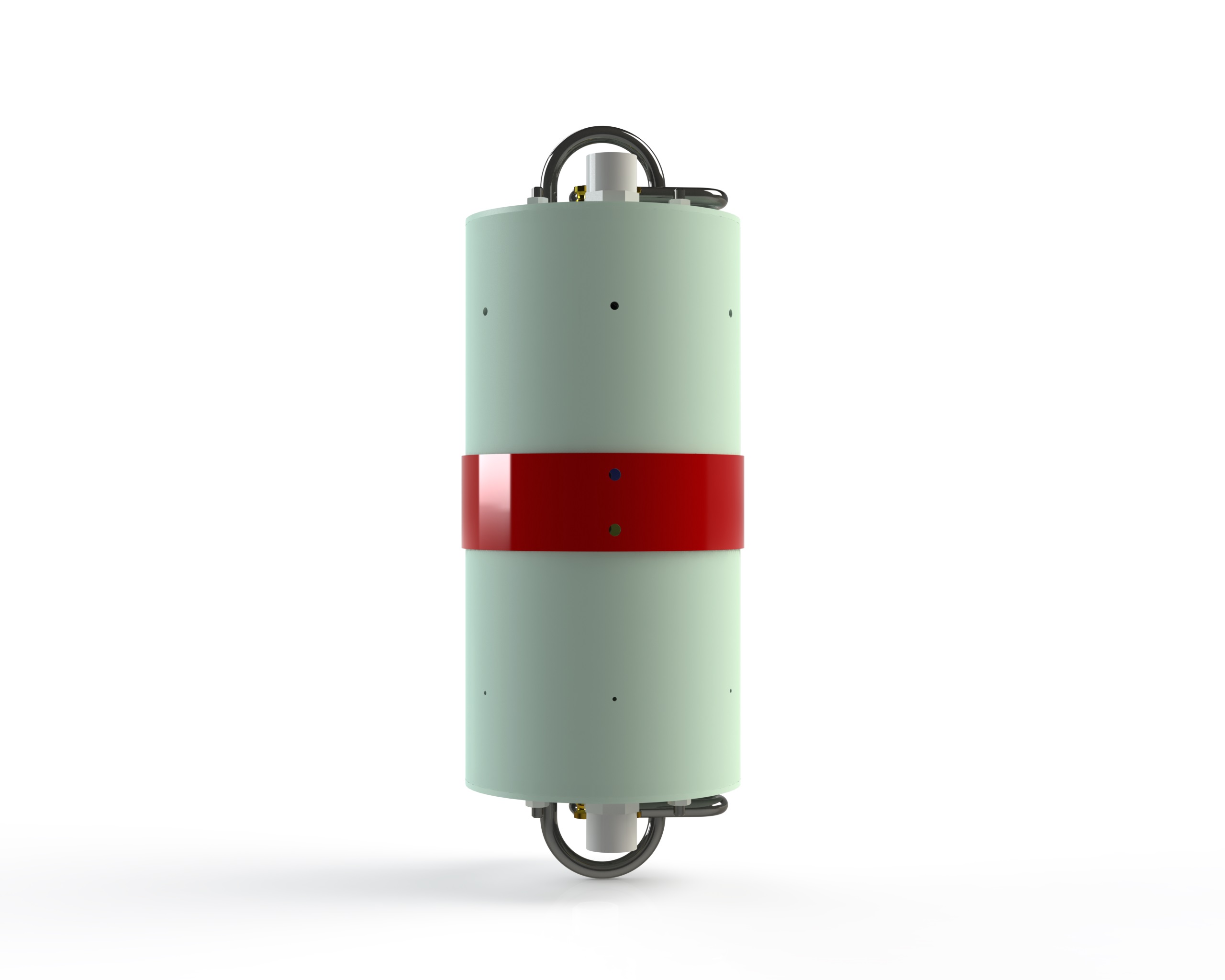
The electronics bay is made from fiberglass tubing like the rest of the rocket. The switch band is a 2.0in (50.8mm) long section of 6.17in (157mm) OD, 6.0in (152mm) ID, G10 airframe tube from Madcow Rocketry. The internal coupler is a 12in (304.8mm) long section of 6.0in (152mm) OD G10 coupler tube, also from Madcow. Bulkheads on the top and bottom of the electronics bay are made by layering an outer fiberglass bulkhead on an inside plywood bulkhead. The outer bulkhead has the same OD as the coupler tube and the inner bulkhead has the same OD as the ID of the coupler. This allows the inner bulkhead to center the bulkheads on the coupler and provide a better seal to prevent residue from the black powder charges from entering the internal volume.
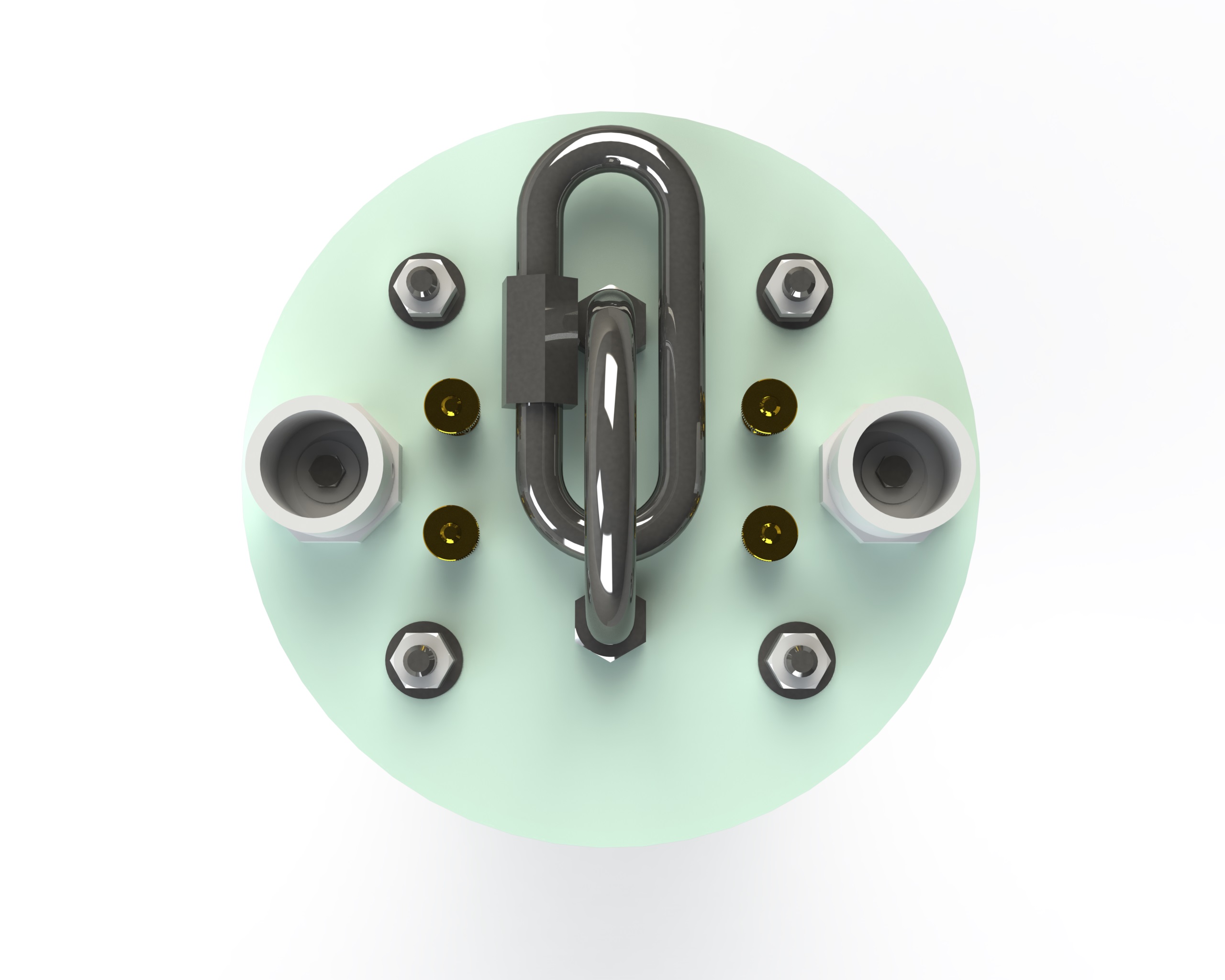
3/8-16 thread size, 2in ID, 2.625in height U-bolts are installed on both the top and the bottom bulkheads. These U-bolts are rated for up to a 1075lb (4782N) load and attach through the outer fiberglass and inner plywood layers. The bulkheads are held onto the coupler by four 1/4-20 threaded rods. Stainless steel nuts on both sides of the top set of bulkheads fix the threaded rods to the bulkhead to ease assembly. Once slid into the coupler, the lower bulkhead is slide over the threaded rod and then into the coupler tube. Another set of stainless steel nuts then are tightened on the threaded rods to hold the assembly together.
Altimeters
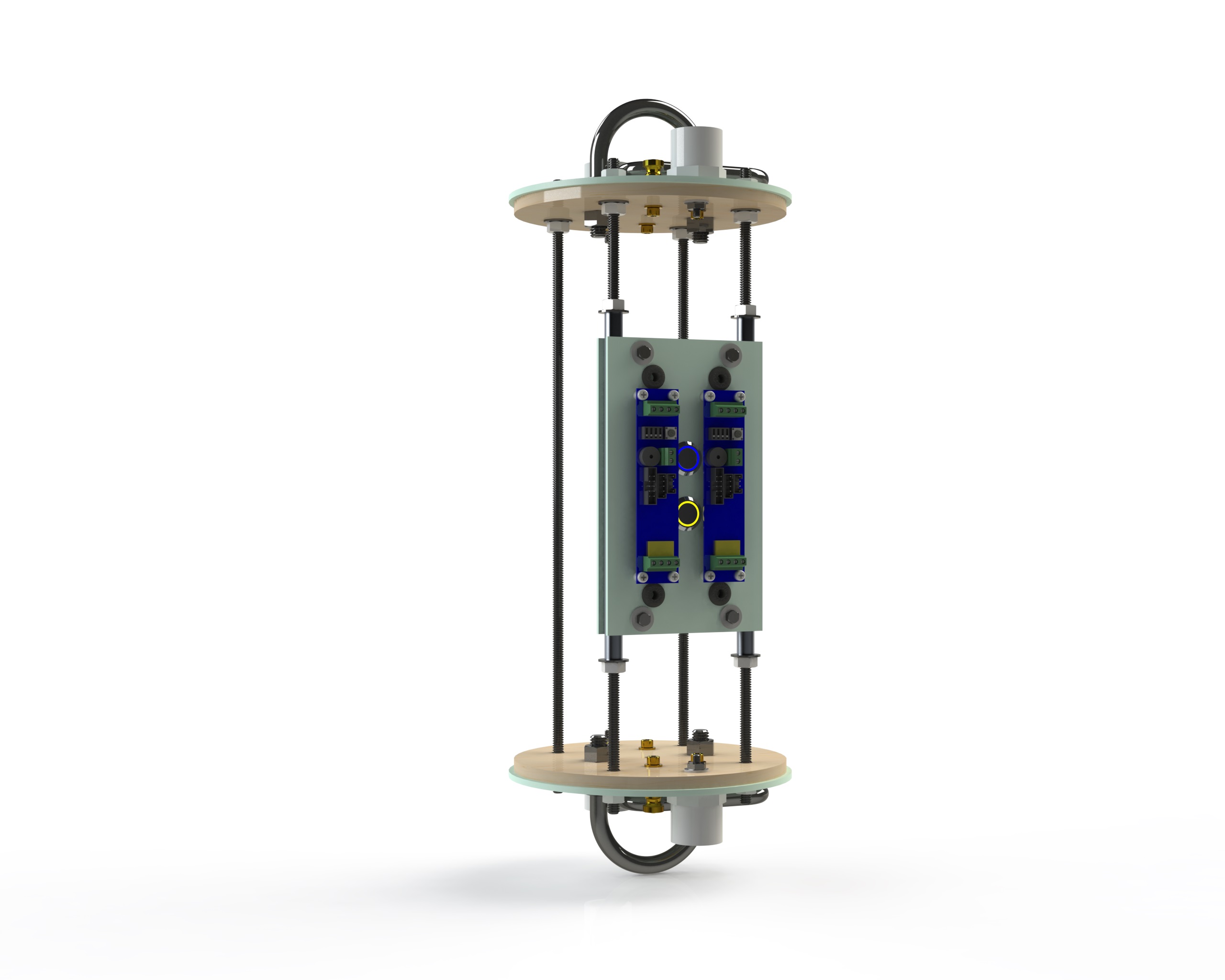
The altimeters chosen are the Missile Works RRC3 Xtreme. One of these altimeters has been used on all of my level 2 flights in my BigEZ and CadRoc airframes. The second altimeter has only been used on a single flight so far but was the backup on a successful redundant dual deploy test flight. Each altimeter has an independent power switch. The switches are latching metal push buttons from SparkFun. The upper switch turns on the primary altimeter and the lower switch the backup altimeter. The blue and yellow rings around the switches are LEDs that illuminate when the batteries are connected to the altimeters. This assists in locating the switch inside the electronics bay when the rocket is on the launch pad as well as providing a visual indication that power is supplied.
The altimeters are fixed to a sheet of 0.093in (2.4mm) thick G10 fiberglass via four 4-40 nylon pan head screws. They are spaced off the surface of the fiberglass with 0.188in (4.8mm) long nylon spacers. This sheet of fiberglass is then secured to two 7.0in (178mm) lengths of 0.375in (9.5mm) OD, 0.277in (7.0mm) ID aluminum 6061-T6 tubing by way of West Systems 105/205 epoxy resin and hardener. These aluminum tubes slide over two of the threaded rods and are secured in position by stainless steel nuts above and below. The dimensions of the fiberglass sheet were designed such that the entire altimeter internal assembly could be test flown inside the 3.94in (100mm) ID electronics bay of my BigEZ airframe.
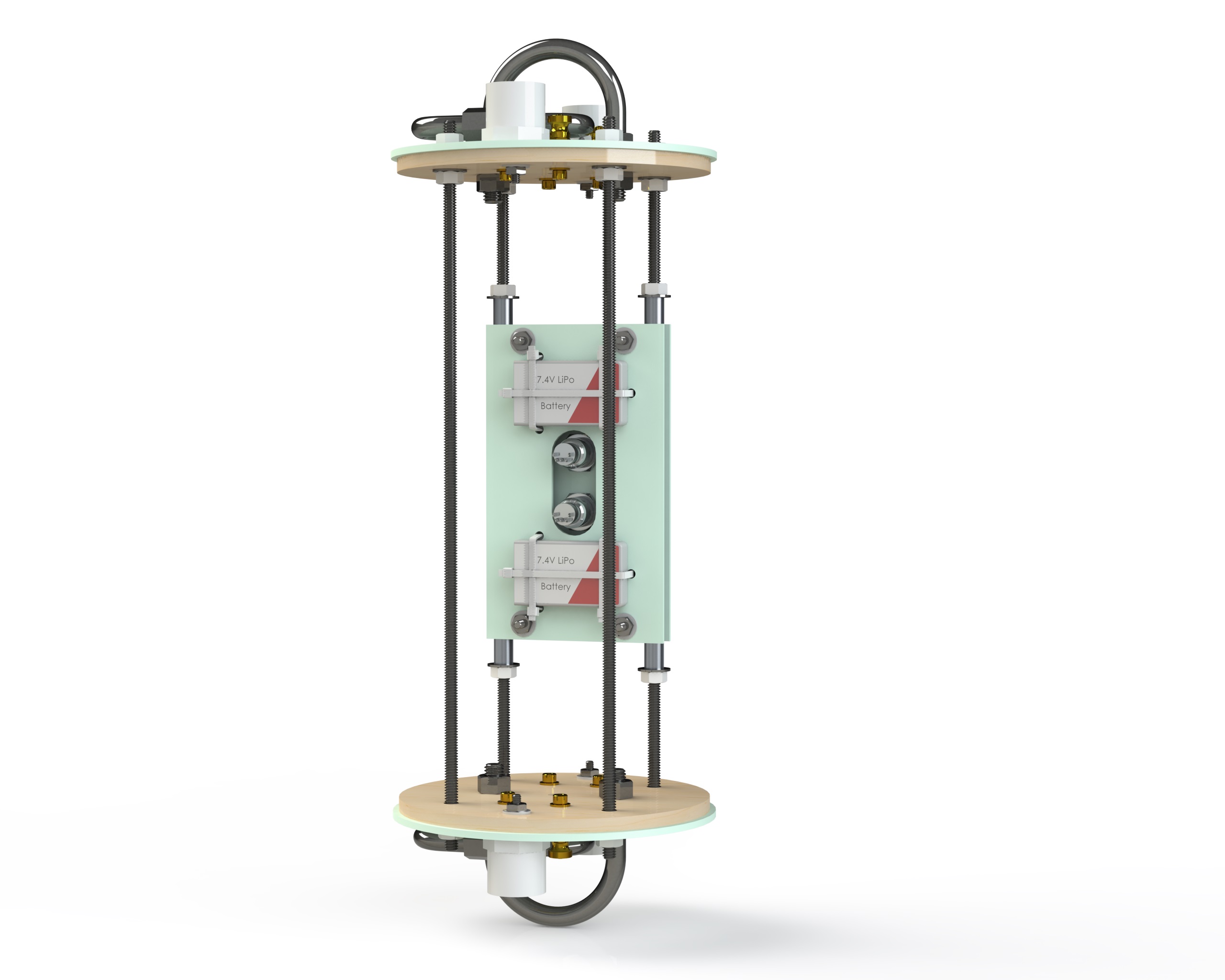
The batteries chosen are 7.4V lithium polymer batteries. These were chosen for their small size, light weight and the reliable connection of the JST connectors. These were chosen after the initial test flight of the altimeter assembly resulted in the 9V batteries that had been used to power the altimeters becoming disconnected after successful deployment of the parachutes. One of the batteries was dislodged from its connector by the force of the main parachute’s backup black powder charge and the other battery disconnected when the electronics bay hit the ground. The flight was still a success and no damage was done to the airframe. All previous flights with the RRC3 altimeters used a much larger lithium polymer battery and they did not suffer from battery disconnects during flight, therefore I decided to return to LiPo batteries for the L3 certification attempt.
The batteries are held onto a second sheet of G10 fiberglass via three zip ties each. This fiberglass sheet is then secured to the other fiberglass sheet via 4 8-32 bolts and nuts. 0.375in (9.5mm) long spacers are used between the two fiberglass sheets to prevent the sheets from bowing under the stress caused by tightening the nuts.
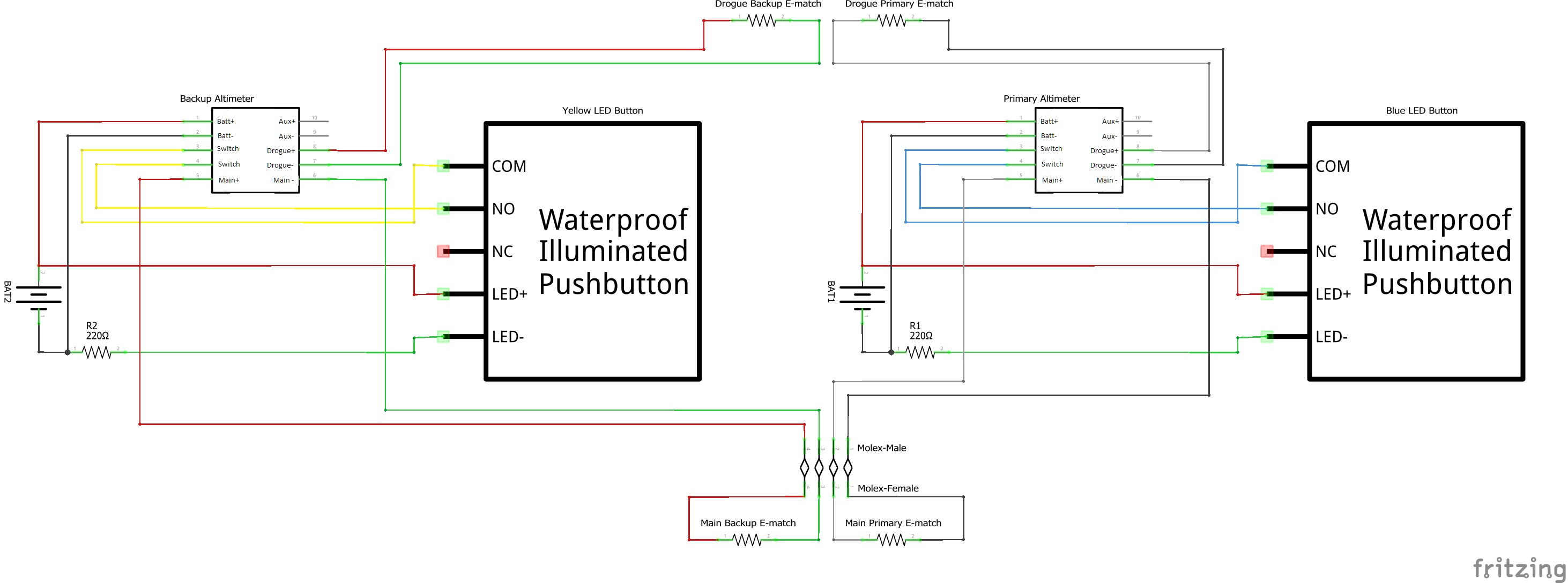
The ejection charges are contained inside four 0.75in size PVC end caps secured to the top and bottom bulkheads. The ejection charges are ignited via e-matches controlled by the altimeters. In order to keep the electronics bay sealed, the electrical signals pass through the bulkheads via brass 8-32 screws. The e-matches are secured two these screws by brass knurled thumb nuts. The internal connection from the altimeters to the brass screws is made two sets of sheathed four wire bundles. Each bundle is labeled on its sheathing and the wires are color coded for the primary and backup charges. The bottom bundle connects to the main parachute’s primary and backup charges and the upper bundle to the drogue parachute’s charges. The inner wires connect the brass screw via a crimped and soldered #8 ring terminal. The bottom wire bundle also has a locking Molex connection inline to allow for simpler assembly of the electronics bay.
Altimeters Wiring
Extra Space for Future Expansion
The other two threaded rods can also support a similar assembly for additional electronics in the future.
Bill of Materials
Click the part number in the table to either view the part’s drawing if it is a custom design, or to view the part on the supplier’s website if it is purchased.
| PART NUMBER | DESCRIPTION | QTY. |
|---|---|---|
| 1-013 | ELECTRONICS BAY COUPLER | 1 |
| 1-014 | ELECTONICS BAY PORT BAND | 1 |
| 1-015 | OUTER BULKHEAD | 2 |
| 1-016 | INNER BULKHEAD | 2 |
| 1-017 | ELECTRONICS SLED GUIDE | 2 |
| 1-018 | ELECTRONICS BAY PLATE | 1 |
| 1-019 | ELECTRONICS SLED | 1 |
| 3043T634 | U-BOLT, 0.375-16 THREAD, 2.375IN HOLE CENTER SPACING | 2 |
| 4880K842 | STANDARD-WALL PVC PIPE FITTING FOR WATER, PLUG WITH EXTERNAL HEX DRIVE STYLE, 1/2 SOCKET MALE | 4 |
| 7130K31 | ZIP TIE | 6 |
| 8233T32 | COMMUNICATION AND SECURITY SYSTEM CABLE, SHIELDED RISER-RATED, FOUR 22-GAUGE WIRES | 3ft |
| 8947T28 | OVAL SHAPED THREADED CONNECTING LINK, TYPE 316 STAINLESS STEEL, 3/8" THICKNESS, 1/2" OPENING, 3900LB CAPACITY | 2 |
| 90107A029 | 316 STAINLESS STEEL WASHER FOR 1/4IN SCREW SIZE, 0.281IN ID, 0.625IN OD | 16 |
| 90675A005 | STEEL LOCKNUT WITH EXTERNAL-TOOTH LOCK WASHER, ZINC-PLATED, 4-40 THREAD SIZE | 8 |
| 91841A009 | 18-8 STAINLESS STEEL HEX NUT, 8-32 THREAD SIZE | 8 |
| 91845A029 | 18-8 STAINLESS STEEL HEX NUT, 1/4"-20 THREAD SIZE | 16 |
| 92314A199 | 18-8 STAINLESS STEEL HEX HEAD SCREWS, 8-32 THREAD SIZE, 1" LONG | 8 |
| 92671A009 | BRASS HEX NUT, 8-32 THREAD SIZE | 8 |
| 92741A120 | BRASS FLANGED KNURLED-HEAD THUMB NUT, 8-32 THREAD SIZE | 8 |
| 92916A335 | BRASS WASHER FOR NUMBER 8 SCREW SIZE, 0.172" ID, 0.375" OD | 32 |
| 93135A276 | OFF-WHITE NYLON PAN HEAD SCREWS PHILLIPS, 4-40 THREAD, 1/2" LONG | 8 |
| 93465A199 | BRASS SOCKET HEAD SCREW, 8-32 THREAD SIZE, 1" LONG | 8 |
| 94639A402 | OFF-WHITE NYLON UNTHREADED SPACER, 3/8" OD, 3/8" LONG, FOR NUMBER 8 SCREW SIZE | 4 |
| 94639A704 | OFF-WHITE NYLON UNTHREADED SPACER, 3/16" OD, 3/16" LONG, FOR NUMBER 4 SCREW SIZE | 8 |
| 94744A224 | ZINC-PLATED STEEL WASHER FOR SOFT MATERIAL, NUMBER 8 SCREW SIZE | 16 |
| 9600K23 | SBR RUBBER PUSH-IN GROMMET, FOR 5/16" ID AND 3/32" MATERIAL THICKNESS | 4 |
| 98007A110 | ADHESIVE-MOUNT NUT, ZINC-PLATED STEEL, 8-32 THREAD SIZE | 6 |
| 99065A120 | GRADE B16 MEDIUM-STRENGTH STEEL THREADED ROD, 1/4"-20 THREAD SIZE | 4 |
| 8054T15 | WIRE, 18GA STRANDED | 4ft |
| 69665K72 | EXTRA-GRIP RING TERMINALS, NONINSULATED, FOR 22-18 GAUGE AND NUMBER 8 SCREW | 8 |
| RRC3X | RRC3 XTREME ALTIMETER | 2 |
| COM-11972 | METAL LATCHING PUSHBUTTON, BLUE LED | 1 |
| COM-11974 | METAL LATCHING PUSHBUTTON, YELLOW LED | 1 |
| COM-10969 | RESISTOR, 220Ω, 1/4W (FROM ASSORTED RESISTOR KIT) | 2 |
| PRT-09353 | HEAT SHRINK, ASSORTED COLORS AND SIZES | 8in |
| 16-02-0077 | SL CRIMP TERMINAL, SERIES 70021, MALE, WITH 0.38µM SELECTIVE GOLD (AU) PLATED CONTACT, 24-30 AWG | 4 |
| 50-57-9404 | SL CRIMP HOUSING, SINGLE ROW, VERSION G, POSITIVE LATCH, 4 CIRCUITS | 1 |
| 70058-0087 | SL CRIMP TERMINAL, FEMALE, 22-24 AWG, WITH 0.38µM SELECTIVE GOLD (AU) PLATED CONTACT | 4 |
| 70107-0003 | SL WIRE-TO-WIRE CRIMP HOUSING, SINGLE ROW, VERSION A, WITHOUT MOUNTING EARS, 4 CIRCUITS | 1 |
| N/A | 2S 7.4V 450MAH 20C LIPO BATTERY PACK | 2 |
| N/A | 20 AWG JST PLUG CONNECTORS, 2 PIN MALE AND FEMALE WITH WIRE LEADS, SET OF 10 PAIRS | 2 |
| 105 Epoxy Resin/205 Fast Hardener | EPOXY FOR ADHESIVE NUTS | 6 |