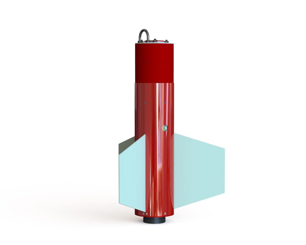
The fin can section subassembly is responsible for five roles that are crucial for the success of the rocket:
- Provide a secure way of mounting the motor into the airframe that is capable of withstanding the large loads induced by the motor.
- Securing the rail buttons used to guide the rocket along the launch rail during the first moments of flight.
- Mounting large enough fins to provide aerodynamically stabilized flight. The fins themselves also need to be able to withstand the speeds the vehicle achieves in flight without flutter. The fin mounts also need to be stiff enough to provide a rigid base for the fins and strong enough to withstand any forces exerted on them during flight and landing without plastic deformation or breaking.
- Providing a secure method for attaching the main parachute to the airframe.
- Securely attaching to the rest of the airframe to prevent any undesired separation during flight.
Motor Mount
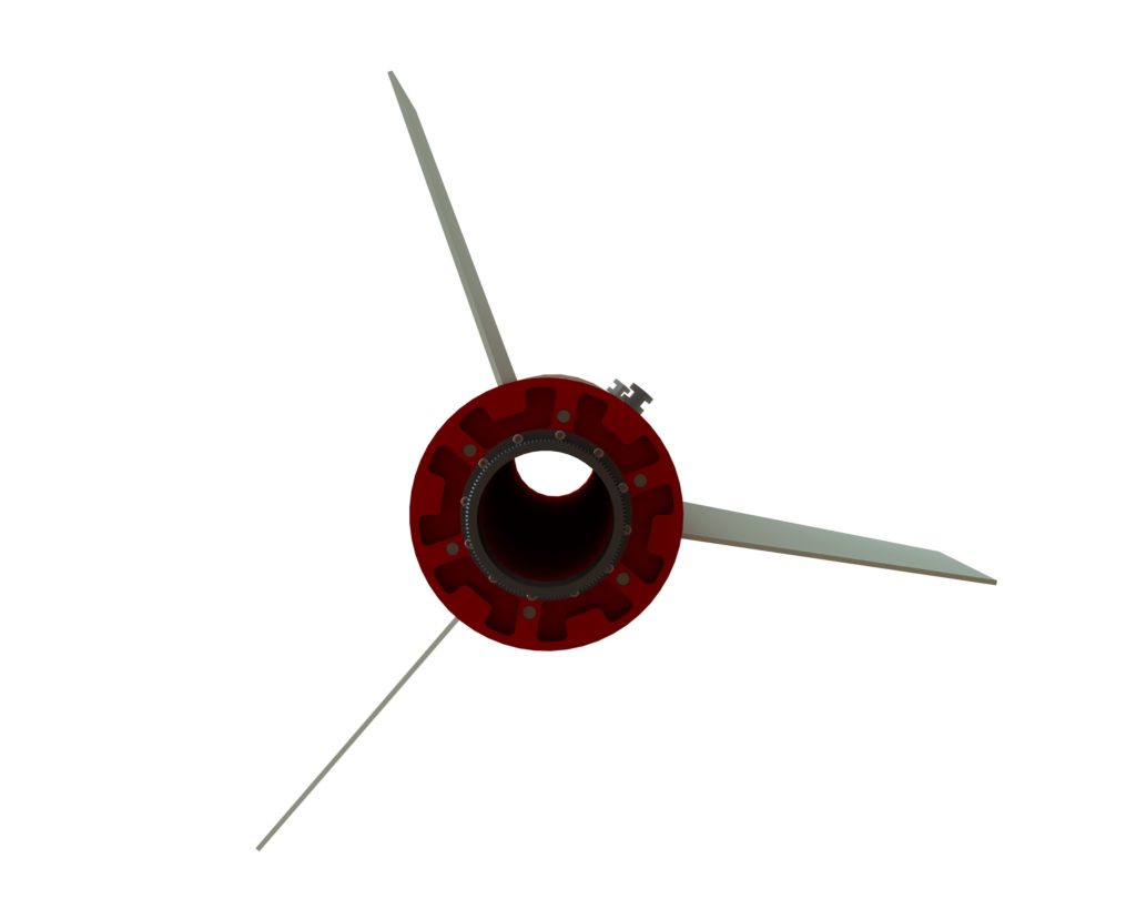
The motor chosen for the certification flight is a 75mm diameter Aerotech DMS M1350W. This motor is TRA certified and is 25.12in (638mm) long. The tube used to center the motor in the fin can section is 3in (76.2mm) nominal diameter G12 fiberglass airframe tube from Madcow Rocketry. The motor is retained inside this tube using an Aero Pack 75mm flanged motor retainer. The retainer is attached via twelve 6-32 size machine screws to a custom thrust plate.
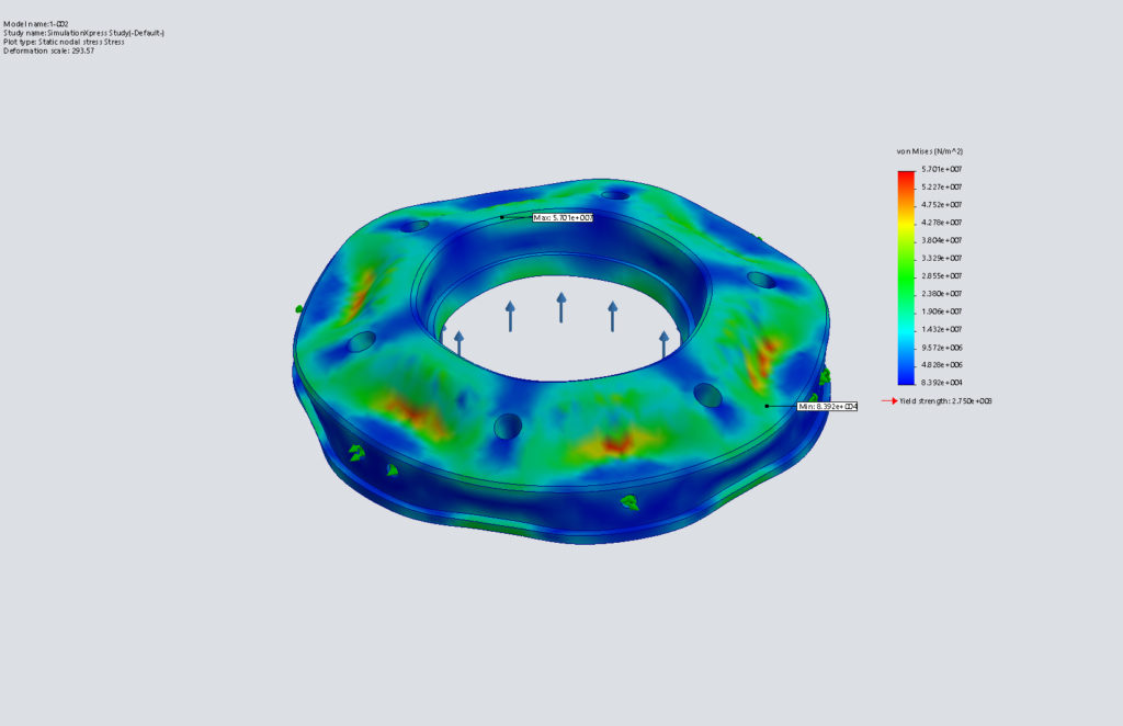
The thrust plate is machined from 6061-T6 aluminum and is designed to handle loads in excess of 1000lbs (4448N) while still providing a safety factor of four. The thrust plate attaches to the outer airframe tube via nine 8-32 flat machine screws as well as to the fin mounts and the top of the assembly via three 3/8-16 threaded rods.
Rail Buttons and Launch Rail
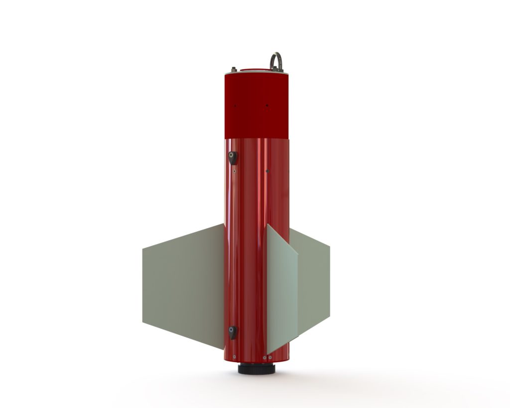
The rail buttons selected are large aerofoiled rail buttons available from Apogee Components and are designed for 1515 size or 1.5in (38mm) cross-section extruded aluminum launch rails. The rail buttons attach to the vehicle via a 1/4-20 flat head machine screw through each rail button and the airframe which threads into an adhesive mount nut inside. The airframe is made from G10 fiberglass tubes from Madcow Rocketry. The outer section is 6.17in (157mm) outside diameter (OD), 6.0in (152mm) inside diameter (ID) airframe tube and the coupler is 6.0in OD (157mm), 5.78in (147mm) ID. The two rail buttons are separated by 16in (406mm). The entire fin can section subassembly, from motor mount to the top of motor mount tube is 28.3in (718mm) long.
Fins and Fin Mounts
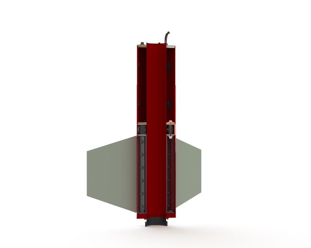
The fins are made from 0.125in (3.18mm) thick G10 fiberglass with a trapezoidal shape. The trapezoidal shape was used to facilitate calculating the critical flutter speed since derivations of the necessary equations are readily available for this geometry. These equations were provide by John D Sahr in the Apogee Peak of Flight Newsletter issue 411. The values in the U.S. Standard Atmosphere Heights and Temperatures tables were used in these calculations to determine the critical speeds at different elevations. The critical speed for the fins was found to be 700mph (1127kph or 313m/s) at sea level or 743mph (1196kph or 332m/s) at an elevation of 4000ft (1219m). The full calculations for this critical fin flutter speed can be found here.
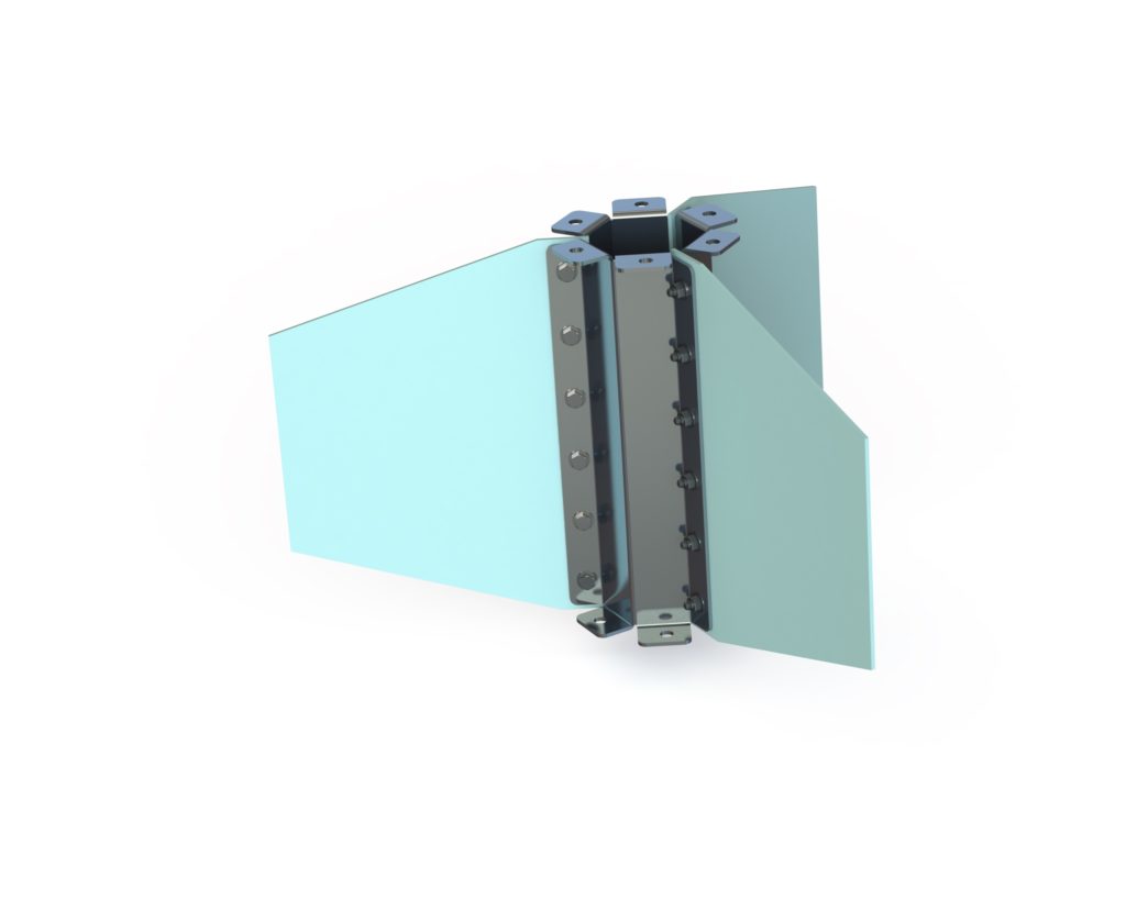
The fins fit through slots in the outer wall of the airframe and are attached to custom designed sheet metal fin mounts via six 1/4-20 hex bolts per fin. These mounts are made from 5052-H32 aluminum and are designed to sandwich the fins and fit snugly on the motor mount tube once the hex bolts are tightened. The assembled mounts and fins are then secured to the thrust plate via three 3/8-16 threaded rods and three 3/8-16 hex bolts. An analysis of the strength of the fins and the bolts that hold them to the fin mounts can be found here.
Main Parachute Mount
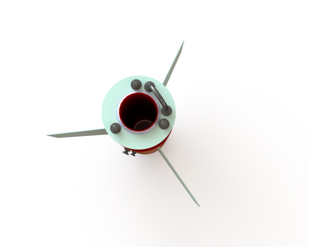
The main parachute and its shock cord attach to the fin can section by way of a 3/8-16 thread size, 2in ID, 2.625in height U-bolt. This U-bolt is rated for 1075lb (4782N) load and it attaches through the outer fiberglass and inner plywood centering rings. Nuts and washers will be used on both sides of these centering rings to securely mount the U-bolt to the rings. The centering rings are also secured to the bottom thrust plate via three 3/8-16 threaded rods mentioned earlier. Since the load can be transferred directly from the top bulkheads, through the fiberglass coupler, into the polycarbonate window for the camera and its surrounding bulkheads (discussed in detail later) and then into the fin mounts, the three nuts on the top of the fin can section will secure the entire fin can section together along its longitudinal axis.
Airframe Attachment
The fin can section is secured to the main parachute bay by way of six 8-32 flat head screws. Each of these screws thread into adhesive mount nuts inside the tube coupler.
Camera Module
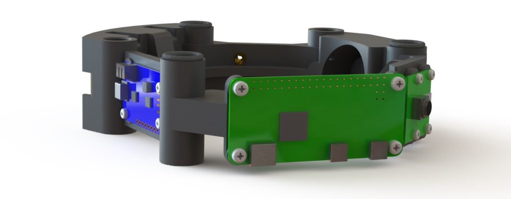
The camera module is designed around a Raspberry Pi Zero W and Pi Camera. In order to provide the regulated 5V power needed to run the Pi, an Adafruit PowerBoost 1000 will be used along with a 1200mAh 3.7V LiPo battery. A small SPST rocker switch will be used to enable the power output on the PowerBoost, turning on the Pi. Once booted, the Pi will act as a local wifi router and serve a webpage with the controls to start/stop video recording. Since the PowerBoost has low voltage detection and a digital out that can signal the Pi that the battery is low, the camera will continue to record video until either stopped manually or the low battery signal is received. The Pi will then save the file and shutdown.
All of the components of the camera bay are mounted to a custom, 3D printed structure that is only 1.45in (36.8mm) tall and fits inside the polycarbonate window tube. The motor mount tube is installed inside this structure. The camera module sits just above the fin mounts, with fiberglass centering rings above and below, and three 3/8-16 threaded rods go through the module’s structure to help align it the port on the outer airframe tube. Three additional 3/8-16 bolts secure just the camera module to the fin mounts for additional rigidity. In order to take up some tolerance buildup and make sure that module does not move axially during flight, three ultra-soft (50A durometer) O-rings are installed above the camera module between it and the top bulkhead. These will be compressed by 28% nominally when the bolts are tightened.
Camera Module Wiring Schematic
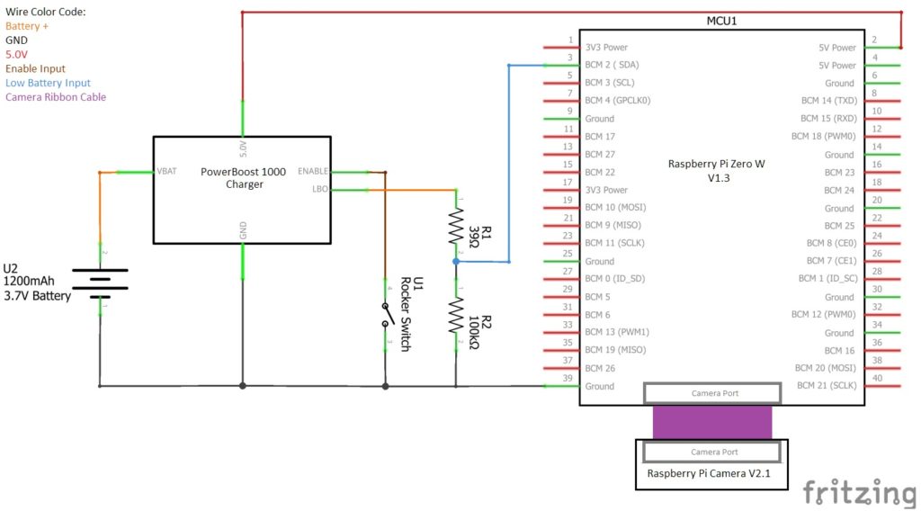
The wiring of the camera module is quite simple. The PowerBoost module converts the 3.7V from the LiPo battery to a regulated 5.0V for the Raspberry Pi Zero. The enable pin on the PowerBoost is connected to one leg of the switch and the other leg is tied to ground. The Raspberry Pi is connected directly to the Pi Camera via a short ribbon cable.
To turn on the camera, the switch brings the PowerBoost’s enable pin to ground. When the PowerBoost is on, the low battery output signal remains at the battery voltage until the battery is below 3.2V. Since the battery voltage can exceed the 3.3V that the Raspberry Pi’s GPIO can handle, a voltage divider is used to limit the GPIO input voltage to 3.0V at maximum when the battery is fully charged and 2.3V right before battery is fully depleted. Since the Raspberry Pi’s maximum input low specification is 2.0V, the voltage divider should never cause an erroneous low battery signal.
Bill of Materials
Click the part number in the table to either view the part’s drawing if it is a custom design, or to view the part on the supplier’s website if it is purchased.
| PART NUMBER | DESCRIPTION | QTY. |
|---|---|---|
| 1-001 | FIN MOUNT | 3 |
| 1-002 | THRUST PLATE | 1 |
| 1-003 | CUSTOM FIN | 3 |
| 1-004 | UPPER FIN BULKHEAD | 2 |
| 1-005 | CAMERA WINDOW | 1 |
| 1-006 | FIN CAN COUPLER CENTERING RING, LOWER | 1 |
| 1-007 | FIN CAN COUPLER CENTERING RING, UPPER | 1 |
| 1-008 | UPPER FIN CAN COUPLER BULKHEAD | 1 |
| 1-009 | MOTOR MOUNT TUBE | 1 |
| 1-010 | FIN CAN SECTION COUPLER | 1 |
| 1-011 | FIN CAN SECTION BODY TUBE | 1 |
| 1-027 | CAMERA SUPPORT STRUCTURE | 1 |
| 13069 | RAIL BUTTON, LARGE, 1.5IN RAIL, AIRFOILED | 2 |
| 24069 | AERO PACK 75MM FLANGED RETAINER BODY AND RING | 1 |
| 3414 | RASPBERRY PI ZERO W V1.3 CAMERA PACK - INCLUDES PI ZERO W (CASE NOT USED) | 1 |
| 2465 | ADAFRUIT POWERBOOST 1000C REV B - 2 | 1 |
| 258 | ADAFRUIT LITHIUM ION POLYMER BATTERY - 3.7V 1200MAH | 1 |
| COM-11138 | SPARKFUN ROCKER SWITCH - SPST ROUND | 1 |
| 8054T15 (or similar) | WIRE, 18GA STRANDED | 4ft |
| 2418T119 | OIL-RESISTANT SOFT BUNA-N O-RINGS 1/16 FRACTIONAL WIDTH, DASH NUMBER 013 | 3 |
| 3043T634 | U-BOLT, 0.375-16 THREAD, 2.375IN HOLE CENTER SPACING | 1 |
| 90107A029 | 316 STAINLESS STEEL WASHER FOR 1/4IN SCREW SIZE, 0.281IN ID, 0.625IN OD | 39 |
| 91247A635 | MEDIUM-STRENGTH GRADE 5 STEEL HEX HEAD SCREW ZINC-PLATED, 3/8IN-16 THREAD SIZE, 2-3/4IN LONG, PARTIALLY THREADED | 3 |
| 91845A029 | 18-8 STAINLESS STEEL HEX NUT 1/4IN-20 THREAD SIZE | 21 |
| 92141A031 | 18-8 STAINLESS STEEL WASHER FOR 3/8IN SCREW SIZE, 0.406IN ID, 0.875IN OD | 19 |
| 92196A146 | 18-8 STAINLESS STEEL SOCKET HEAD SCREW 6-32 THREAD SIZE, 3/8IN LONG | 12 |
| 92240A541 | 18-8 STAINLESS STEEL HEX HEAD SCREW 1/4IN-20 THREAD SIZE, 7/8IN LONG | 18 |
| 92703A304 | 18-8 STAINLESS STEEL TORX FLAT HEAD SCREWS 8-32 THREAD SIZE, 3/8IN LONG | 9 |
| 92703A310 | 18-8 STAINLESS STEEL TORX FLAT HEAD SCREWS 8-32 THREAD SIZE, 3/4IN LONG | 6 |
| 92703A414 | 18-8 STAINLESS STEEL TORX FLAT HEAD SCREWS 1/4IN-20 THREAD SIZE, 1-1/4IN LONG | 2 |
| 92865A623 | MEDIUM-STRENGTH GRADE 5 STEEL HEX HEAD SCREW ZINC-PLATED, 3/8IN-16 THREAD SIZE, 7/8IN LONG | 3 |
| 94510A360 | BRASS SCREW-TO-EXPAND INSERTS FOR PLASTICS FLANGED, M2 X 0.4 MM THREAD SIZE | 8 |
| 94510A370 | BRASS SCREW-TO-EXPAND INSERTS FOR PLASTICS FLANGED, M2.5 X 0.45 MM THREAD SIZE | 6 |
| 94842A103 | MEDIUM-STRENGTH STEEL FLANGE NUT GRADE 5, ZINC-PLATED, 3/8IN-16 THREAD SIZE | 9 |
| 94879A104 | OFF-WHITE NYLON PHILLIPS SCREWS M2 X 0.4 MM THREAD, 8 MM LONG | 8 |
| 94879A876 | OFF-WHITE NYLON PHILLIPS ROUNDED HEAD SCREWS M2.5 X 0.45 MM THREAD, 8 MM LONG | 4 |
| 98007A110 | ADHESIVE-MOUNT NUT ZINC-PLATED STEEL, 8-32 THREAD SIZE | 12 |
| 98007A200 | ADHESIVE-MOUNT NUT ZINC-PLATED STEEL, 1/4IN-20 THREAD SIZE | 2 |
| 98750A458 | GRADE B7 MEDIUM-STRENGTH STEEL THREADED ROD 3/8IN-16 THREAD SIZE, 27.25IN LONG | 3 |
| 105 Epoxy Resin/205 Fast Hardener | EPOXY FILLET, AROUND MOTOR MOUNT TUBE | 2 |